FM VERİCİ

Sitemize Hoşgeldiniz sitemizin kuruluş sebebi Eğitim Öğretim Bilgilendirme amaçlıdır Site içerik ve kaynalar Çeşitli Web Sitelerinden Derlenmişolup Teylif Hakları Çerçevesinde Korunuyor Olabilir Şayet bugibi durumlarda lütfen Site Yönetimiyle İrtibata geçiniz Saygılar Hikmet TURNA

Latest Post

06:06 ,
Another low-level hack on my Android Apad ( clone/fake Apad? ).


This time it's now with the 800x480 GLCD driver. It's working, but I'm not sure if the initialization is complete (i.e. the hardware is, most probably, already initialized by the bootloader). I've just modified the sources from Wondermedia (look at "\common\wmt_logo\" folder). LCD routines here are not using the graphics engine (GE) of WM8505.


download Eclipse project here:  ARM9_WM8505_LCD.zip


Read my previous post on how to set-up the tool-chain and how to load the program on WM8505.


    expected output:


forum link: Re: Let's learn ARM using cheap 7" tablets


08:07 ,
 My first step in learning the ARM9 platform.


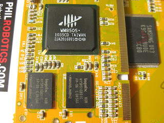
VIA / WonderMedia's WM8505 (ARM926EJ-S):


UART0 Connection:


Serial console connection details:  Project Gus


Required Tools:  all are free =) 


The goal is to run this simple code: (main.c)


 It should output these strings on UART_0 port, just like this:


 After setting up the tools, here are the next steps:

-Create new project on Eclipse


 -Select target processor (WM8505 is a ARM926EJ-S processor)


-Select binary format for the flash image:


-linker setting:


 - after building the project, open the generated *.map file to verify the linker output


    *I don't know, yet, what's with this 0x03F80000 address.

      This is the load address used by Wondermedia version of U-BOOT


- Complete Eclipse project files:


download here: ARM9_WM8505_UART0.zip


* most of the hardware initializations (e.g. clock settings) are already done by the bootloader,

   so we don't have to worry about them for now.


Next question is, "how to load and run the code?


I've tested two ways of how to transfer the generated image to the RAM:


First is through tftp transfer, second is SD card load during boot-up.

Both method uses the bootloader, which is already present in the board (in the SPI flash).


My board got v1.1.4 of U-BOOT.


1. TFTP transfer to RAM.


- get a copy of this freeTFTPD32 server application.


- using the LAN adapter, connect board to host PC Ethernet


enter u-boot console, and type these commands:


* RAM load address can use other than 0x0


2. SD card scriptcmd

-guide:  How to edit "scriptcmd"

-during boot-up, the u-boot will read the "scriptcmd" script in the "script" folder of the SD card.


*these commands can also be typed in the uboot console. ("mmcinit" must be sent first)


references:

Wondermedia GPL sources

WM8505 datasheets

forum link:

Let's learn ARM using cheap 7" tablets


MARG (Magnetic, Angular Rate, and Gravity) sensor array used for AHRS (Attitude and Heading Reference Systems).


Android OpenGL 3D display on Samsung Spica (i5700).


Sparkfun 9DOF sensor stick SEN-10389, later replaced by SEN-10321.


Using ATmega328P, operated at 3.3V supply and 8MHz crystal. At this speed, reading sensors' measurements and computing "AHRSupdate" take about 31ms to complete. Default compiler setting is used on WinAVR. With 25Hz sampling rate, this leaves mega328p extra 9ms to do other tasks. Bluetooth SPP (serial) communication is buffered and interrupt driven, so no processing time is wasted in reading and sending data to the android phone.


References:


(1) Sebastian Madgwick's Alternative AHRS (MARG) algorithm - Quaternion implementation of Mayhony's DCM filter incorporating magnetic distortion compensation.


(2) Fabio Varesano's FreeIMU. Also using Madgwick's implementation of the DCM filter on Arduino platform.


(3) Rotation convertions by Martin Baker. Very good discussion on quaternions and other 3D representation like Euler angles and transformation matrix.


(4) OpenGL Transformation Matrix by Song Ho Ahn


(5) Similar discusion on diydrones.com started by Harinath


Android project examples:


Android Bluetooth


Bluetooth Chat


Android OpenGL Projects


OpenGL ES tutorial


Android Bluetooth Oscilloscope


Special thanks to the generous guy who gave me these toys, Thank you very much!


Bu aralar üzerinde çalıştığım bir rf projesi için teknik bilgiler ararken UDEA tarafından hazırlanmış türkçe dokümanlara ulaştım. İlk dokümanda bir rf modülün uygulamada nasıl kullanılması gerektiği en ince noktalara kadar anlatılmış. Sizlerinde rf uygulamalarınızda pcb konusunda işinize yarayacaktır. Anten uygulamaları ile ilgili olarakta diğer dokümanda oldukça faydalı olacak bilgiler var.


Instead of drawing only the edges of a polyhedron, this time we draw the faces and 'fill' it with corresponding colors. This demo now uses a dsPIC (16-bit and 40MIPS core) for "faster" and "smoother" graphics in the N6610/N6100 LCD (w/ pcf8833 controller). See "lcd6610.h" for the used pinouts.


There are several ways of "hidden surface removal". The easiest way, and most appropriate for drawing convex polyhedron is the use of Backface culling. "Backface" will determine whether a surface (e.g. triangular face) is need to be drawn or not.

/-----------------------------------------------------------------------------------/

Draw3D routine:


triangle color-fill routine:


(*another version of using dsPIC hardware multiplier/divider is included in the download)


detect whether a triangle is facing backward.


Complete MPLAB+C30 project (dsPIC33FJ16GS504):

n6610lcd_3D_demo_part2.zip


Nokia 6610/6100 LCD 3D projections demo using Microchip's PIC18F25J11.
PIC18F25J11 is clocked at 12MHz external oscillator with 4xPLL enabled.
It's operated at 3.3V supply, same with the LCD (and so, direct connections and higher spi clock rates are possible).


The demo is all about simple 3D projection - no rendering, no raycasting, etc., just the plotting of edges/lines. It displays common polyhedrons like tetrahedron, hexahedron(cube), octahedron, square pyramid, and triangular prism.


"3Ddemo.c"


*based on original sources:

Nokia 6100 LCD with CCS C


3D Vector objects in C using the PIC micro


Microchip C18 project:  n6610lcd_3D_demo.zip


Pic18f2550 ile oldukça ilginç uygulamalar yapılabiliyor. Bu projede sd mmc karta yüklü wav dosyaları pic18f2550 işe okunmuş. Pic18f2550 çıkışına bağlanan bir hoparlör ilede ses sinyalleri verilmiş. Sesi oldukça net, ses kayıt entegreleriyle uğraşmak istemeyenler için ideal bir çözüm olabilir. Aşağıdaki linkten gerekli dosyları (hex, kaynak kodu devre şeması) indirebilirsiniz. Kaynak site burada.


Daha önce ilginç saatler başlıklı bir yazı yayınlamıştım, bu uygulamada devamı sayılır. Bir osiloskobun girişlerine gönderilen siyaller ile saat tasarlanmış. Aşağıdaki linkten uygulama dosyalarını indirebilirsiniz. Kaynak site burada.pic osiloskop saaat devresi dosyalar downloaddevre şeması:Osiloskop saat videosu:


mikro C kaynak kodu:micro c programı sayfası, 900 kelimeye kadar ücretsiz


MKRdezign

İletişim Formu

Ad

E-posta *

Mesaj *

Blogger tarafından desteklenmektedir.
Javascript DisablePlease Enable Javascript To See All Widget